Offers Design Flexibility in a Variety of Configurations
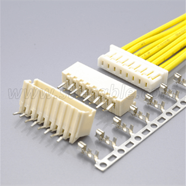
This is offered in different models and various dimensions, with top or side entry configurations that might suit your specific needs.
Top entry configuration consumes a minimum of 8 mm x 4.5 mm mounting height and width, respectively; while side entry configuration consumes a minimum of 4.8 mm x 9.6 mm mounting height and width, respectively.
Over-molded Shell Feature Designed for High Density, High-Speed Harness
Manufactured with higher infill housing, the 2.0mm connector is suitable for high-density and crowded applications, withstanding higher strain and mechanical stress.
A Variety of models to choose from
In addition to the above flexibility in configurations of the 2.0 mm pitch connector, STC also offers this connector with a different number of circuits ranging from 2 to 16 which would suit your specific needs.
An Added Layer of Product Durability and Connector Reliability
No alloy was used in fastening the wires to the board but through the use of a crimping method was, which made it more flexible and mechanically stronger.
The crimps are well-engineered to be air-tight, preventing oxygen and moisture from reaching the metals and causing corrosion. Thus, the connector can be easily removed from the head without holding the wires.
Furthermore, it prevents the cables from being easily disconnected due to entangled routing, heavy loads, or vibration.
Robust and Ruggedized Terminal Enhancements
Reliable electrical connection, even under conditions of low current and low voltage, is guaranteed with its two-point contact design.
Surface Mount Option with Strong Solder Tabs
The two solder tabs ensure the retention of the header to PCB connection and act as a strain relief for the SMT solder tails minimizing the chance of solder joint breakage.
Optimized Safety Feature for Electrical Shock Hazard
With its improved product enhancement, the connector has the capability of withstanding a voltage of 500 V AC per minute, which means that the insulation is sufficient to protect the user from electrical shock, overheating, and fire.
Savvy Material and Finish
The header contact is made up of copper alloy, tin plated over a phosphor bronze material.
The housing is made of Nylon66 UL94V-0 natural ivory. These housings are available with or without protrusions.
The wafer is made up of Nylon66/46 UL94V-0.
The solder tabs are made up of brass, copper undercoated, or tin-plated. These two solder tabs ensure the retention of the header to PCB connection and act as a strain relief for the SMT solder tails minimizing the chance of solder joint breakage.
Vast Temperature Range with Relatively Low Insulation and Contact resistance
There’s a dimple at the center of the contact which ensures positive contact and low contact resistance at all times. Insulation resistance and contact resistance are 100 Mega ohm per minute minimum and 20 Mega ohm maximum, respectively.
The temperature range for this connector is -25 degrees centigrade to +85 degrees centigrade. This range is based on the rise of temperature with increasing current.
Applicable in Chassis Wiring and Power Transmission Wiring
The 2.0 mm Pitch Connector can be used for AC and DC operations with a rated current of 1.0 amperes and 50 Volts. It is applicable in both chassis wiring and power transmission wiring.
Fully Shrouded Header
The pin header of the connector is wrapped with a thin plastic guide box around it good for preventing cable connection mishaps and it also provides good guidance for the mating connector.
Twin U-slot section
The Twin U-slot section or twin-axial cable has a pair of insulated conductors where the conductors run parallel with one another. This is commonly used in high-speed balanced-mode multiplexed transmission in large computer systems, in which the signals are carried by both conductors in a U-shaped configuration. This ensures reliable connection and provides greater noise immunity.
|
